Level editor
The level editor is used to generate the level layouts that are the basis for creating areas. A level layout is a non-interactive resource; the objects placed within it serve only to provide the physical structure and appearance of the area. If you need the player to interact with objects within an area you'll need to use interactive placeables instead.
Note that unlike the Area editor, only two modes of camera control are currently supported: "flycam" mode (![]() button in the toolbar) and 3DS Max mode (
button in the toolbar) and 3DS Max mode (![]() button). NWN style is not currently supported.
button). NWN style is not currently supported.
Contents
Creating a new level
When creating a new level layout you'll be presented with a wizard that sets up several basic attributes. Note that some of these attributes can't be changed once the level has been created.
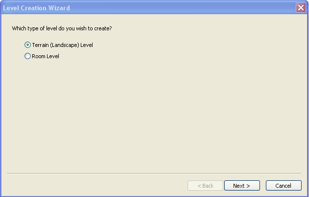
The first choice is whether to have a terrain mesh (the "ground") or not. If you choose to have a room-based level you'll have to place chunks of floor, walls, and ceiling to enclose the player on all sides. Room-based levels have no further attributes that need to be configured during new level creation, so if you select "room-based" you'll be taken straight to the level editor from here.
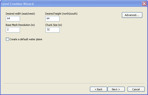
If you choose terrain-based, you'll be asked to define some attributes for the terrain mesh. By default you're shown the basic set of attributes:
- Terrain mesh dimensions, in meters. Note that 64 by 64 is about the minimum that can produce a serviceable level, and that 256 by 256 is the maximum before one starts risking bad performance - though levels can be made larger than this if one takes care.
- Base mesh resolution - determines the size of the individual triangles that make up the terrain mesh. The default has 2 meter triangles. Note however that you'll be able to manipulate the terrain at a much higher resolution than this by using the tessellation tool; each tessellation level splits the previous level's triangles up into four smaller triangles.
- Chunk size - chunks are the basic simulation unit used by the engine. The default 32m is a good chunk size. You'll probably not want to reduce it smaller since you can't have the terrain mesh overhang from one chunk into another; smaller chunks could place limits on the sorts of terrain warping you'll be able to do later.
- Create a default water plane - Creating additional water planes later on is quick and easy, but this option provides a pre-made one by default.
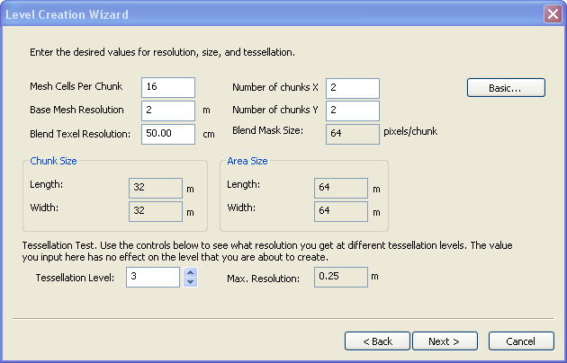
If you click the "advanced" button you'll be provided with a different presentation of the level's dimensions. Instead of defining its dimensions directly you can set how big chunks are and how many chunks there are in each dimension, defining the level's overall dimensions implicitly.
There's one important attribute that can only be set in the advanced pane; the texel map's resolution. A texel is a "texture element", a sort of high-level pixel equivalent that defines a texture instead of just a single uniform colour. The terrain is "painted" with texels, described later.
Layout name
The name of a layout is limited to seven characters. BioWare uses the following naming system:
- Three-letter prefix that describes the region or plot the layout is for. For example, "ost" for Ostagar and environs.
- Three-digit number that uniquely identifies the layout within that region. Increments of one hundred are commonly used for major areas to allow sub-regions to be grouped together.
- A single character identifying variants of the layout. For example, a "d" suffix for the "daytime" version of an exterior layout. "d" is also often used to mean "default", for areas where day and night are irrelevant (deep in a cave, for example).
So for example the layout "ost101d" is a layout in the Ostagar region with a daytime ambience.
Toolbar
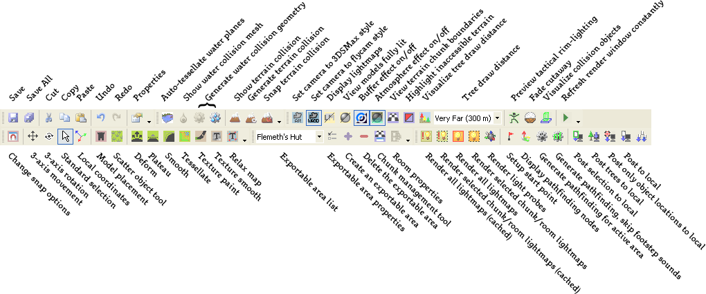
See sections below for detailed information on level editor specific toolbar buttons.
Interior and exterior levels
There are two basic types of levels; interior and exterior. Many features of these two level types are the same and level editor documentation will generally be applicable to both types unless specifically noted. Their key difference is that exterior levels have a terrain mesh (the "ground") and interior levels don't. Note however that there's no reason why you couldn't use one level type to "fake" the other - for example you could create a an entirely underground cave using an "exterior" level with the terrain mesh as the cave's floor.
Terrain mesh
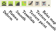
The terrain mesh is a deformable surface used in exterior levels to provide a "ground". This toolbar contains the tools that deals with the terrain mesh:
Each of these buttons brings up a "brush" that's used for various tasks.
 "Deform" allows the terrain mesh to be raised or lowered, or it can extrude the ground "outward" or "inward" along its surface normal. In other words, if you were to apply the brush to the side of a cliff in extrude mode you could create a cave-like hollow or a bulging overhang. Note that the walkmesh used by the game is two-dimensional, ie, it doesn't allow pathfinding both over and under an overhang. The walkmesh will always be generated on the overhanging part of the land. Also note that you cannot have an overhang from one terrain chunk into another terrain chunk - turn on "view chunk boundaries" to check if this has happened and reposition any overhangs that violate these boundaries.
 "Plateau" flattens out the land the brush is applied to, removing bumps or dips and making the ground level. This is a good tool for making a path through rough terrain, or for smoothing out a flat field.
 "Smooth" is a more generic form of flattening tool. It doesn't force the ground toward a horizontal plane, instead just averaging out the nearby terrain in whatever orientation it averages out to.
 "Tessellate" changes the resolution of the terrain's mesh, increasing or decreasing the number of triangles a given region. This allows for a more fine-grained control of the shape of the land and prevents small features from being given obvious straight edges caused by the underlying triangle mesh. Left-clicking increases the number of triangular subdivisions and right-clicking reduces it. The "max level" and "min level" settings on the tool constrain these values - lower numbers indicate a coarser mesh with fewer, larger triangles.
 "Texture paint" paints materials from the material palette onto the terrain. The material palette for any given level can hold up to eight materials, and they can be blended together seamlessly.
 "Texture smooth" blurs the boundaries between different material types, allowing them to fade more gradually from one terrain material type to another.
 "Relax map" causes stretched ground textures to relax back toward their default resolution. Terrain texture stretching can occur when you deform the ground. For example, if you were to stretch the ground upward in a small area to form a tall cliff, the texture on the cliff's face would be vertically stretched and could look unrealistic as a result.
Models
Models are used to create any other objects that may be used as part of the level art - walls, floors, ceilings, non-interactive furnishings, visual effects, etc. To place them click on the ![]() icon in the toolbar to go into model placement mode.
icon in the toolbar to go into model placement mode.
Trees are added using the "scatter object" mode (![]() ).
).
Model palette
The model palette contains all the basic building blocks that you'll have available to build a level layout with. These building blocks are created using third-party 3D studio programs such as 3DSMax, a process that we won't go into here.
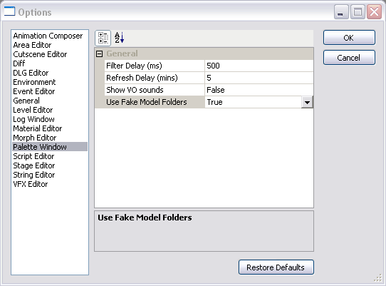
Unlike the database resource palette, the model palette doesn't have a heirarchy of folders and subfolders. Since there are usually a vast number of models available this can make the palette cluttered and difficult to work with. To make it more manageable you should set the toolset's configuration to "fake" a folder structure. The toolset will divide models up based on their names, using underscores as dividers; for example the models dwe_face and dwe_orzent would both be placed inside a "dwe" folder. The option for setting this can be found under the palette options menu:
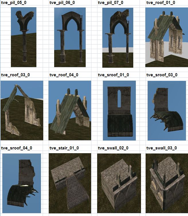
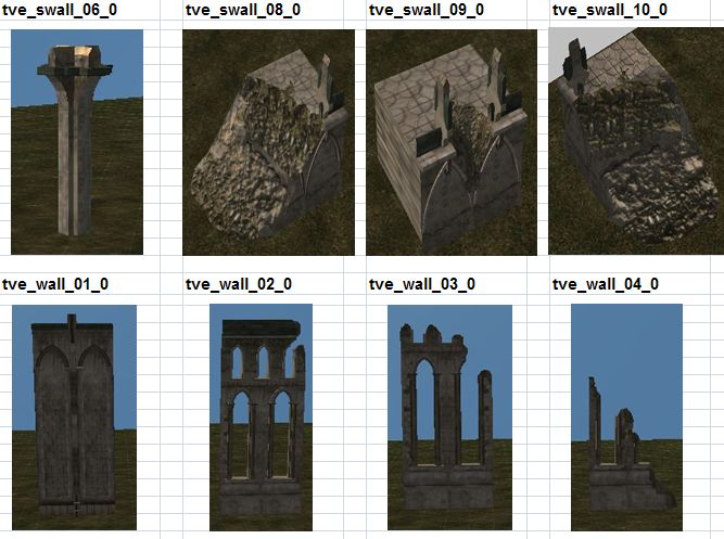
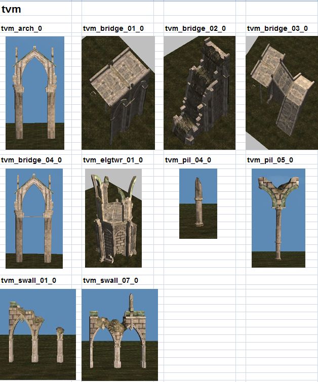
Models are grouped into "tilesets" with pieces that share common structural themes. For example, there might be a "dwarven fortress" tileset that contains a variety of structural pieces and furniture of dwarven manufacture, and a "Tevinter" tileset that contains a variety of pieces with Tevinter architectural motifs.
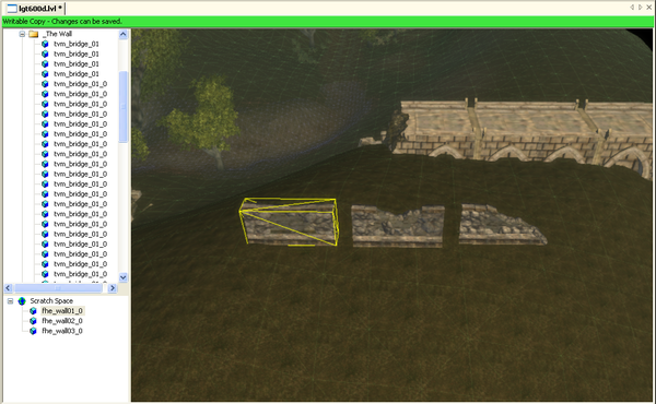
Since the names of these models can often be a bit inscrutable, a more convenient way of working with models that you're frequently using on a level (such as wall segments) is to bring them into the level's "scratch space" and copy them as needed. Objects in the scratch space can be positioned within the level just like ordinary objects but will not be exported when the level is exported for use as an area layout.
Selecting objects
When clicking on models in the layout there will often be other foreground objects that are in the way, preventing the immediate selection of the object you wanted. Simply keep clicking on the same spot to cycle through all of the objects that are underneath the mouse pointer.
Moving and placing objects
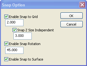
Clicking on the "snap options" button ![]() on the toolbar brings up the following options:
on the toolbar brings up the following options:
"snap to grid" causes the position of objects you place or move to be constrained to specific points in an imaginary three-dimensional grid. This is very useful when placing things such as floor tiles, which must be arranged in a precise grid in order for their edges to match up correctly.
"snap rotation" similarly constrains the rotation of objects to specific angles.
"snap to surface" is useful when placing furniture and other objects on an existing surface (terrain, floor, etc.). It forces the object to rest "on" the surface. Once placed you can disable surface snapping and fine-tune the object's location as needed.
Trees, grass, and shrubberies
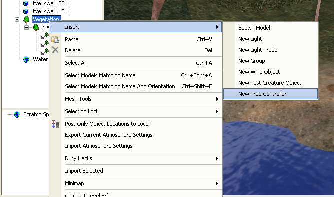
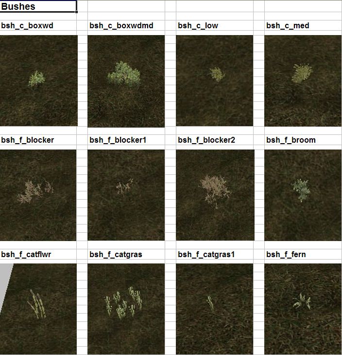
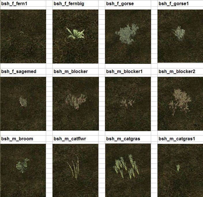
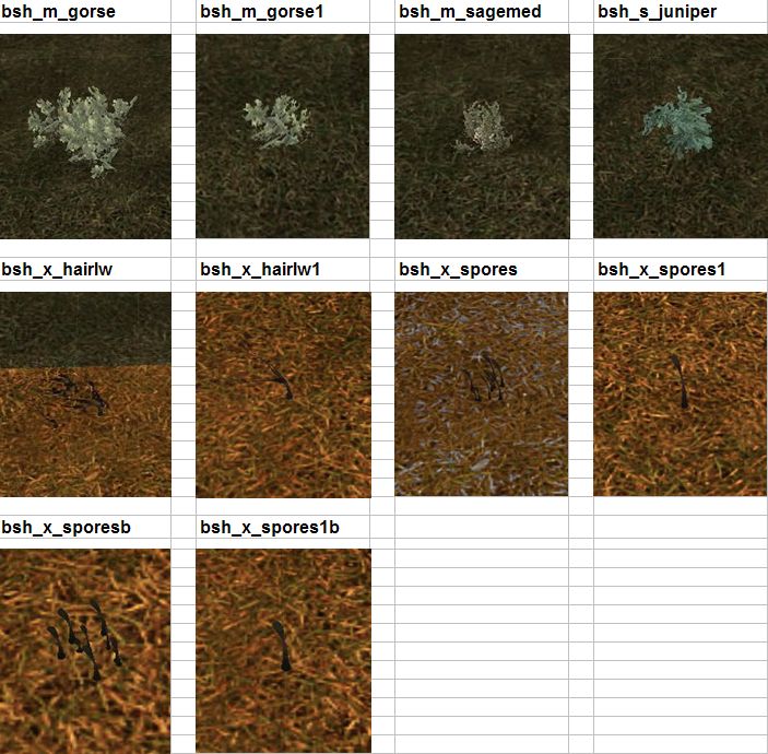
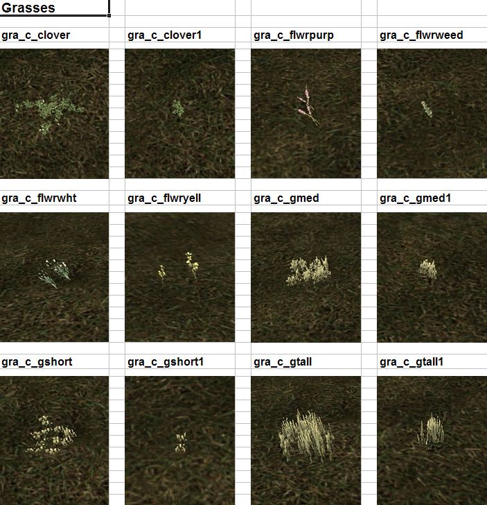
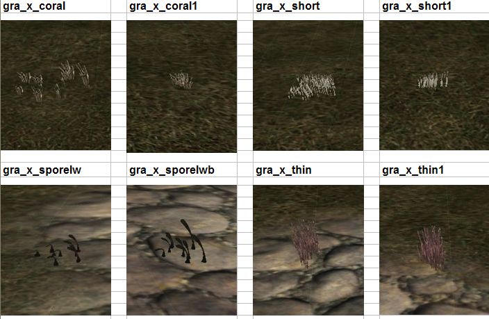
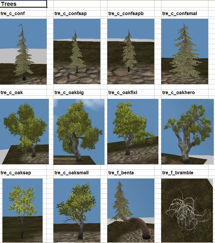
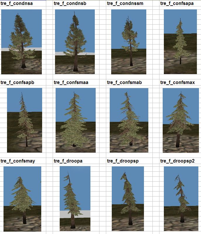
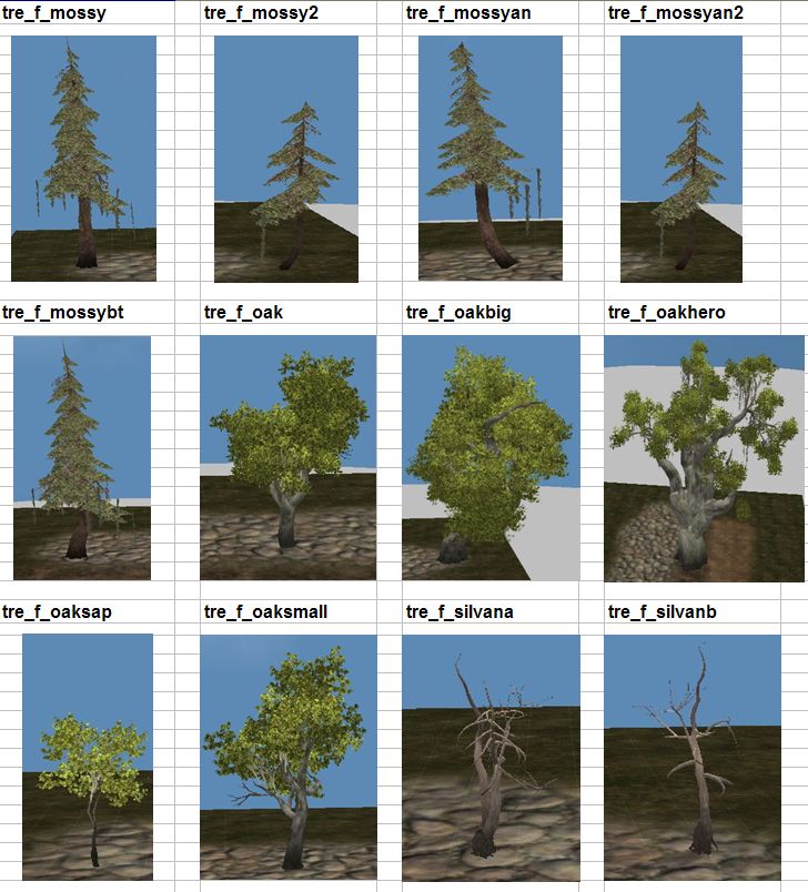
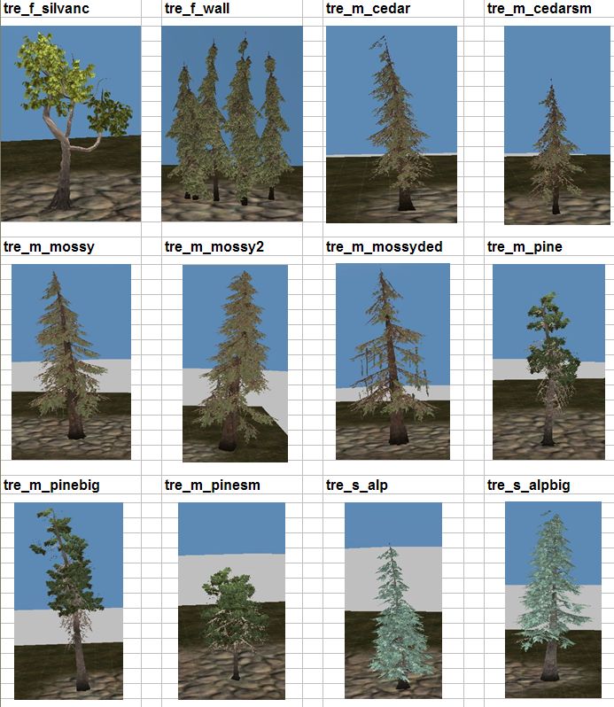
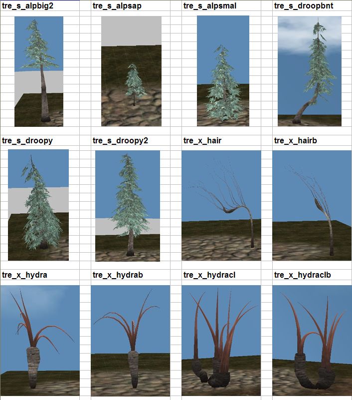
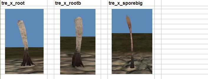
Trees, grass and shrubberies are handled somewhat differently from other models. They are created using a program called SpeedTree that includes information allowing them to respond to the wind. To place trees on a level, you first need to add that tree type's tree controller:
Once this is done you can use the scatter object tool (![]() ) to place specific examples of the vegetation you've added controllers for.
) to place specific examples of the vegetation you've added controllers for.
Light probes
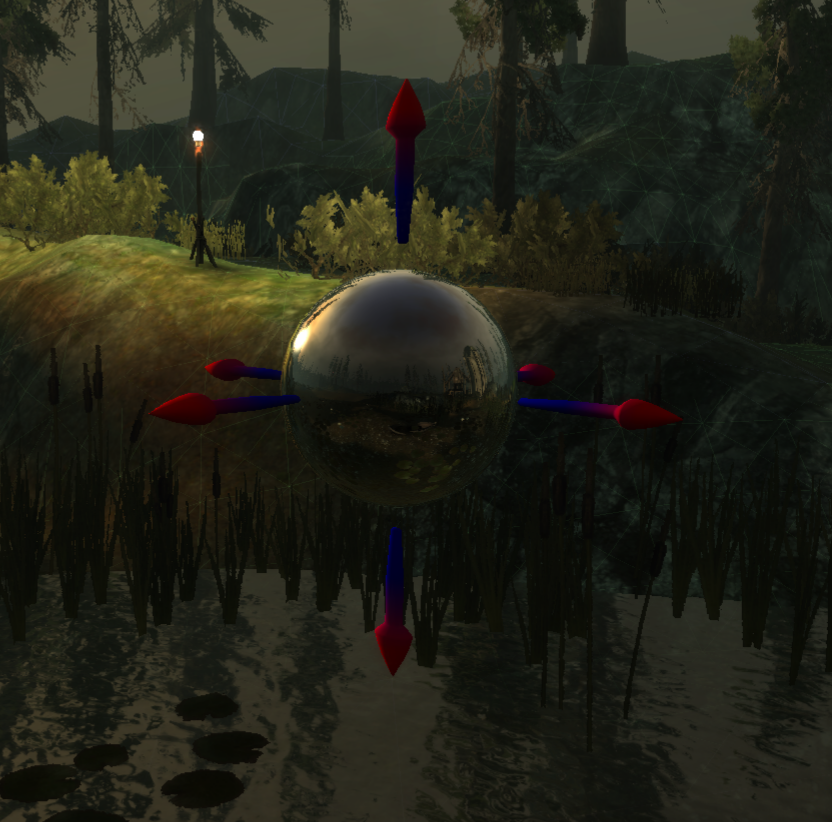
Light probes are used to generate the appearance of nearby reflective surfaces. A light probe consists of an imaginary sphere that is textured with a pre-rendered view of its surroundings in every direction; reflective objects will use the texture of the nearest light probe to produce an approximation of what a reflection should look like. Light probes are particularly important where water planes are used.
The following example shows a light probe with the reflection texture rendered onto it (to make the light probe's texture visible you need to have "view models fully lit" turned off and "display light maps" turned on). The water below the light probe is using the probe's texture to determine its reflection.
If you make any changes to the level that would make a visible difference to what a light probe "sees" you'll have to re-render the light probes to update the reflection texture. This command is under the menu "Tools -> Render -> Render light probes", or you can click the toolbar button ![]()
Pathfinding
Pathfinding is generated by clicking the toolbar button ![]() . The pathfinding process lays down a grid of points that are marked "accessable" if they can be reached from a pathfinding start spot via passable terrain. This is essentially a flood-fill algorithm.
. The pathfinding process lays down a grid of points that are marked "accessable" if they can be reached from a pathfinding start spot via passable terrain. This is essentially a flood-fill algorithm.
To see the existing pathfinding grid, click on the ![]() toolbar button or select "Pathfinding nodes" under the "View" menu.
toolbar button or select "Pathfinding nodes" under the "View" menu.
"Passable" or "impassable" depends on a variety of factors such as the slope of the land, obstructions, or water depth. Accessibility
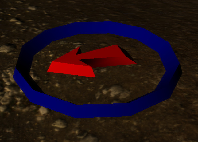
Start points are represented by a blue ring with a red arrow. Note that these are different from waypoints, and are only used by the level editor for pathfinding purposes.
Models will often contain collision volumes that will automatically make the places they're located impassible. Likewise, you can set a certain depth of water as being impassible and pathfinding will take this into account. To manually "fence off" an area, use the "Generate Terrain Collision" tool (![]() in the toolbar) to place invisible barriers that pathfinding will treat as impassible. You should include some sort of visual barrier as well, if possible, to let the player know why he can't pass through that spot.
in the toolbar) to place invisible barriers that pathfinding will treat as impassible. You should include some sort of visual barrier as well, if possible, to let the player know why he can't pass through that spot.
Wind
Each level can have one active wind object in it. The location of the wind object doesn't matter. The wind object defines how wind behaves on this level, which is used for such things as flapping banners and swaying trees.
Black boxes
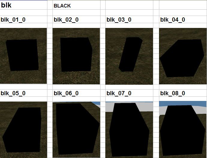
When creating an indoor layout you'll need to manually insert "black box" objects on the outer sides of the layout's walls. This allows the player to see through the walls when the camera is outside them.
Exportable area
A layout requires at least one exportable area. This is the area that the player will be able to operate in and percieve when the layout is exported for use in the game.
It's possible to have a large level with several different exportable areas. The player will have to go through an area transition to travel between exportable areas, just as if they were separate layouts entirely, but by combining them into one level in the level editor it becomes easier to maintain consistency between them. This is particularly useful in layouts where a player in one exportable area can see into the other exportable area but not reach it directly.
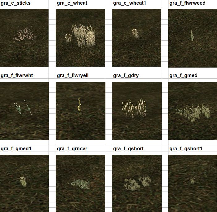
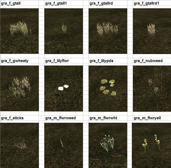
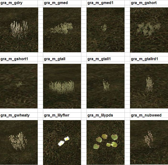
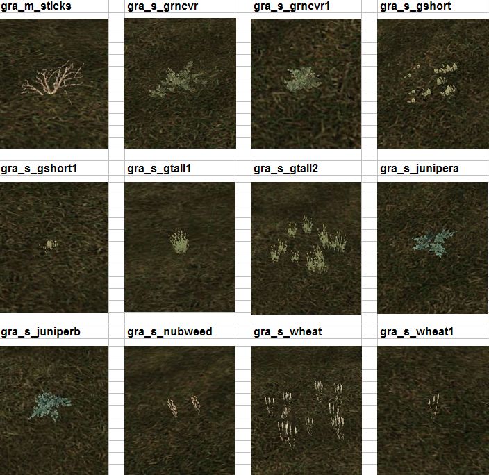
File name and associated 'Vegetation' images
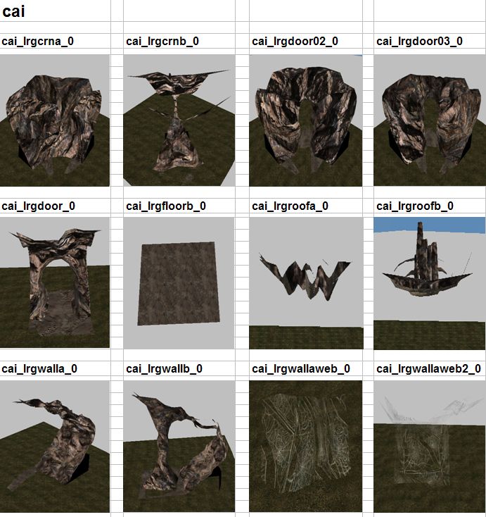
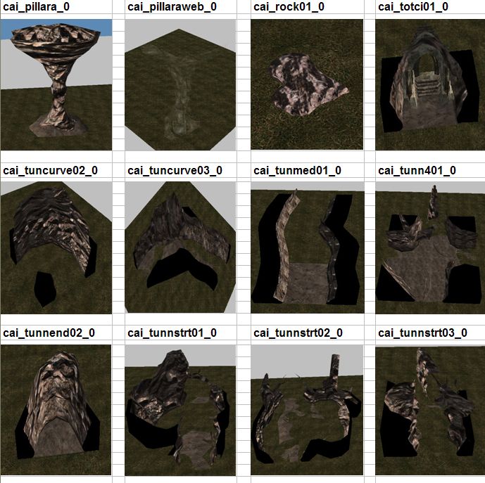
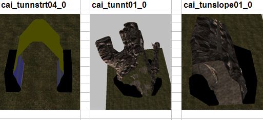
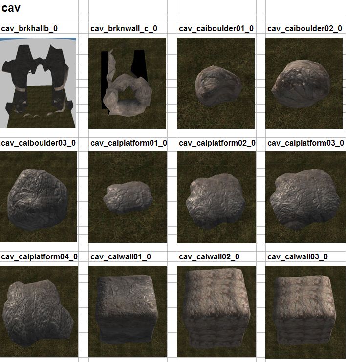
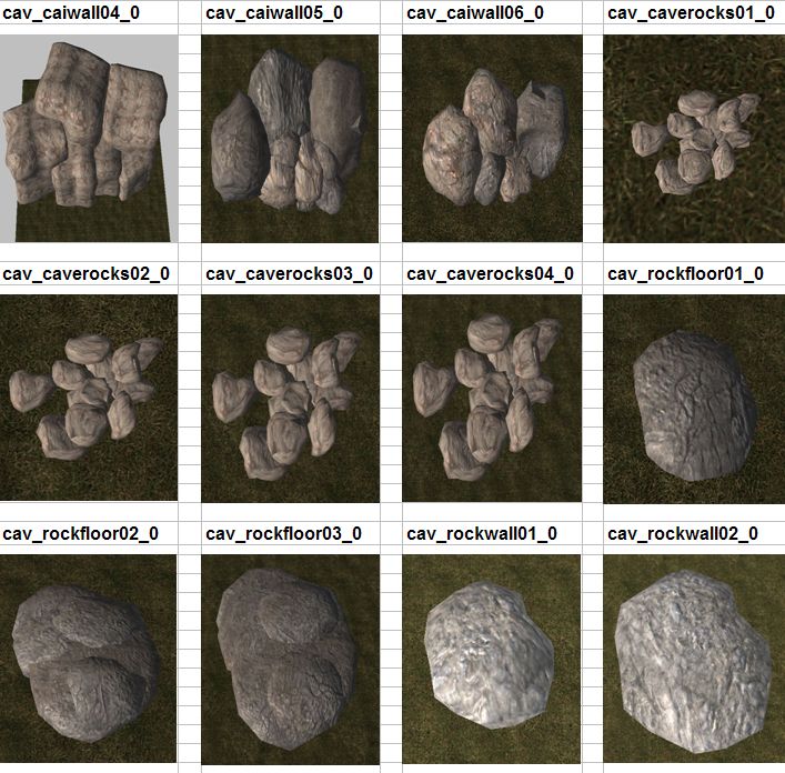
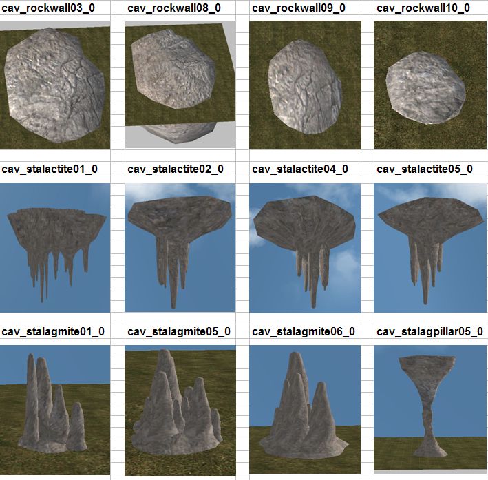
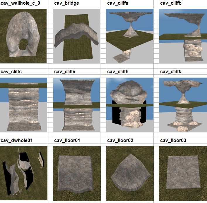
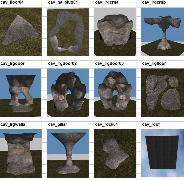
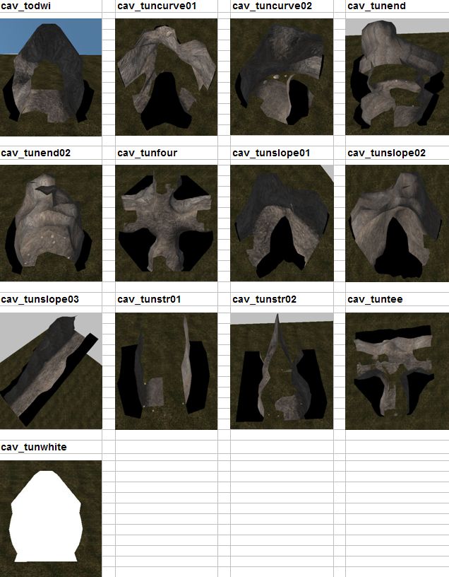
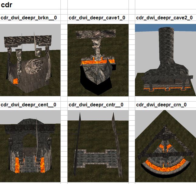
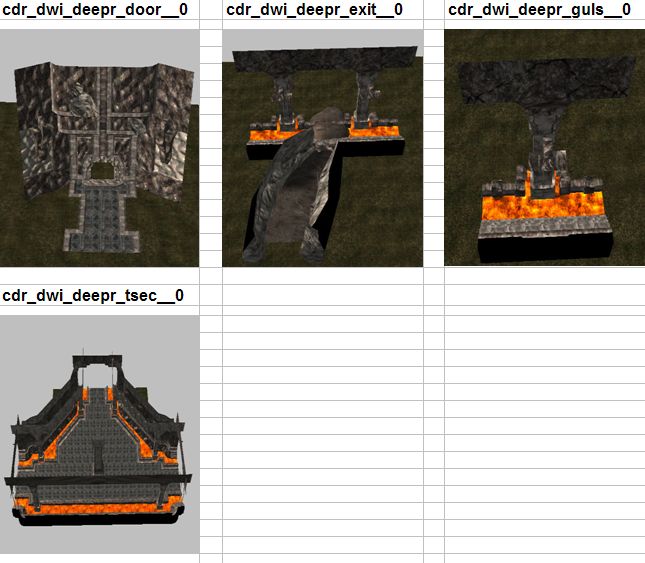
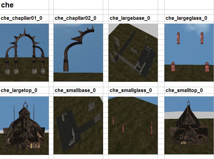
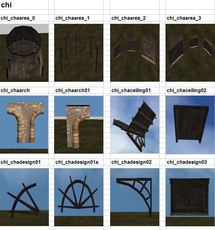
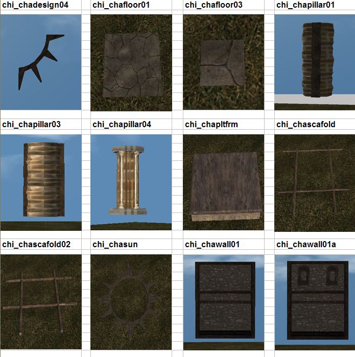
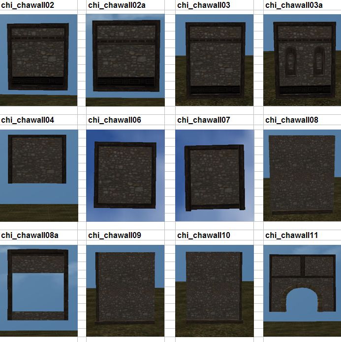
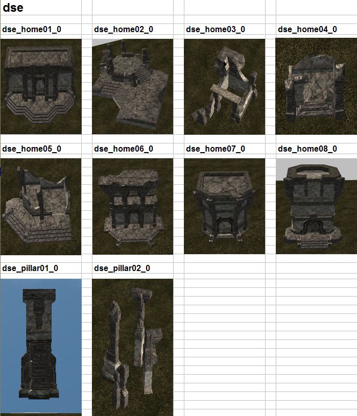
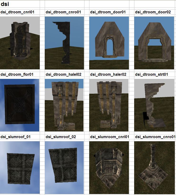
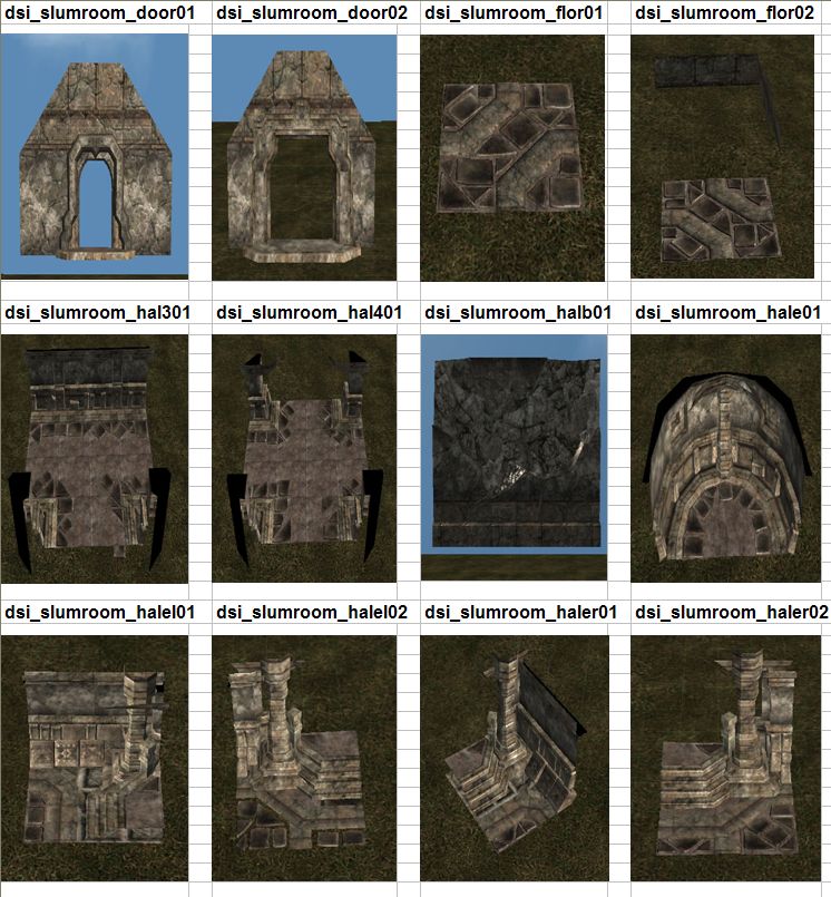
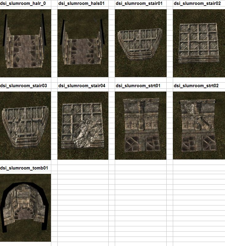
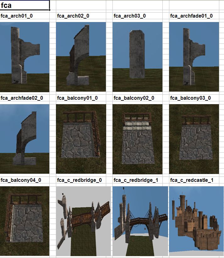
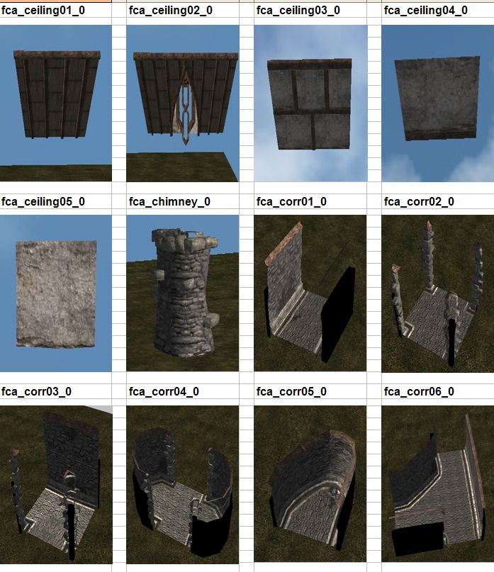
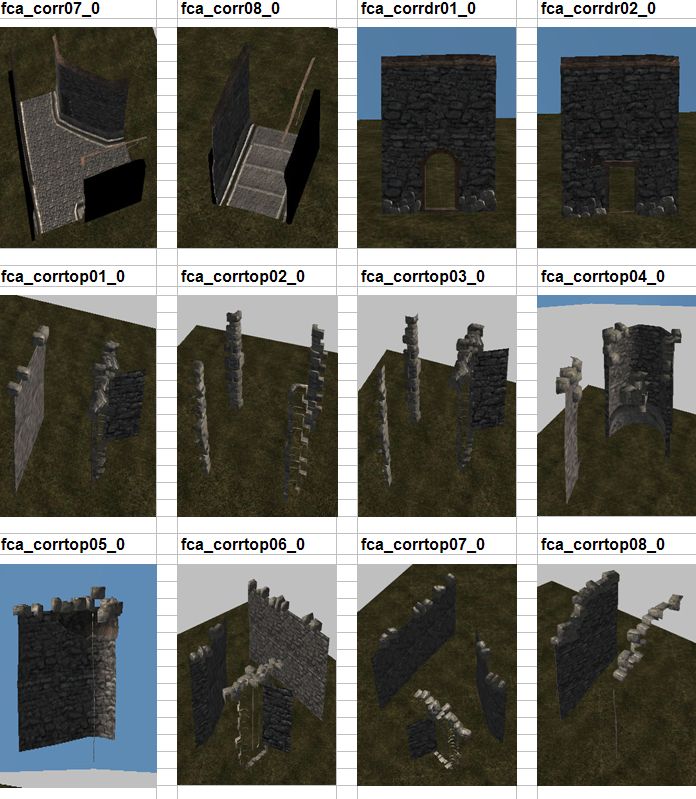
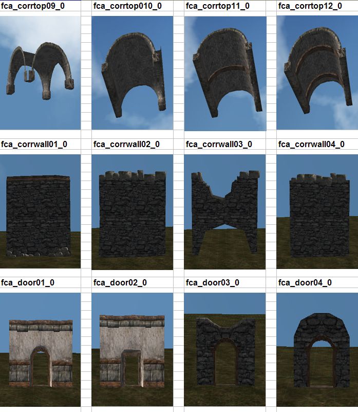
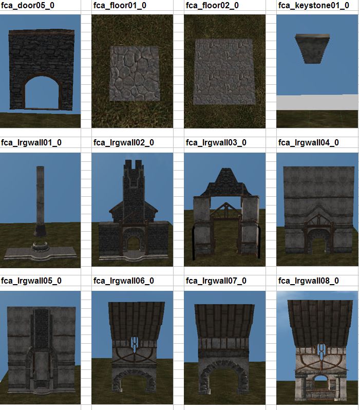
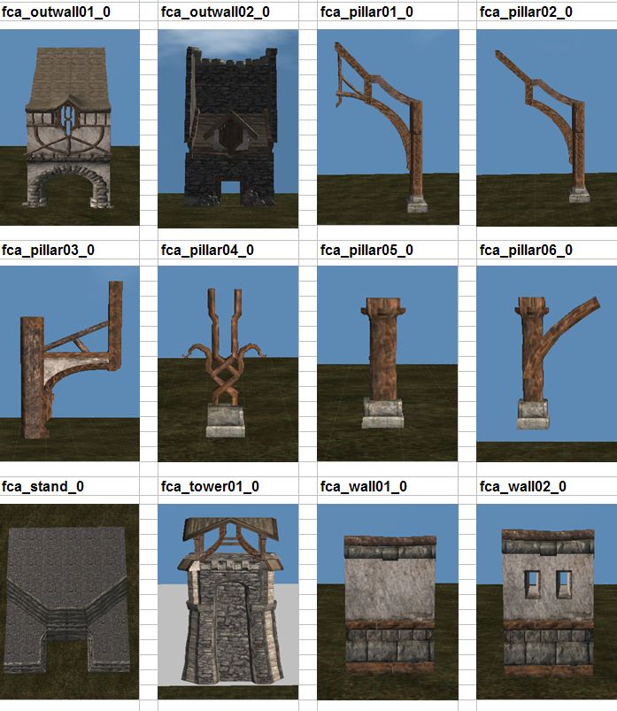
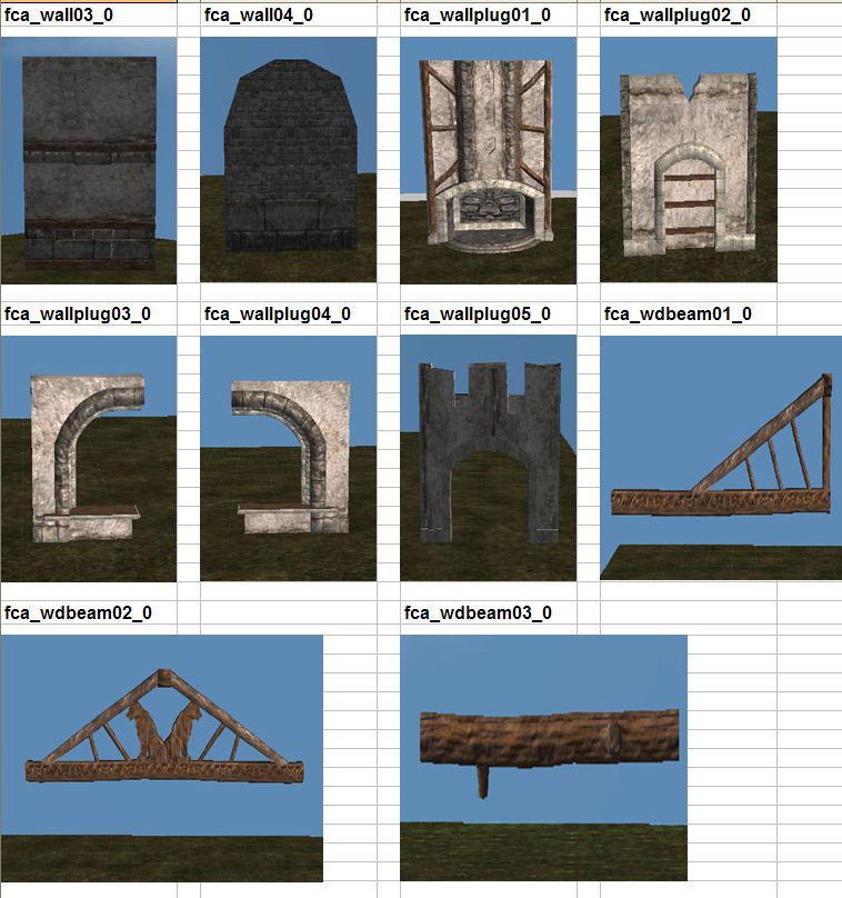
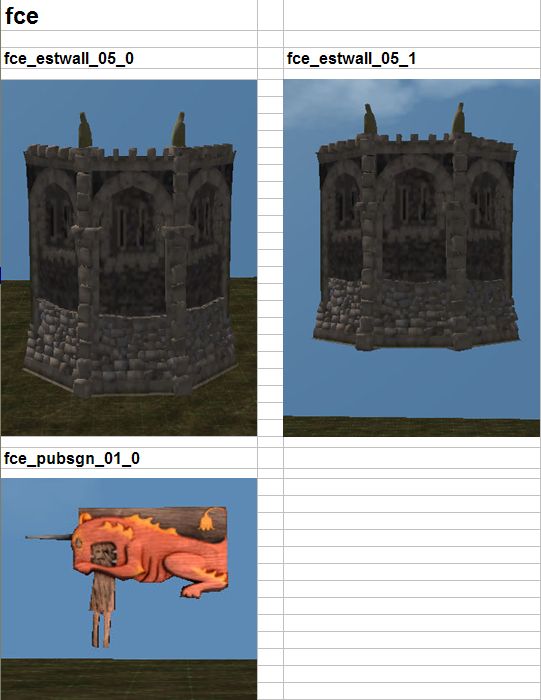
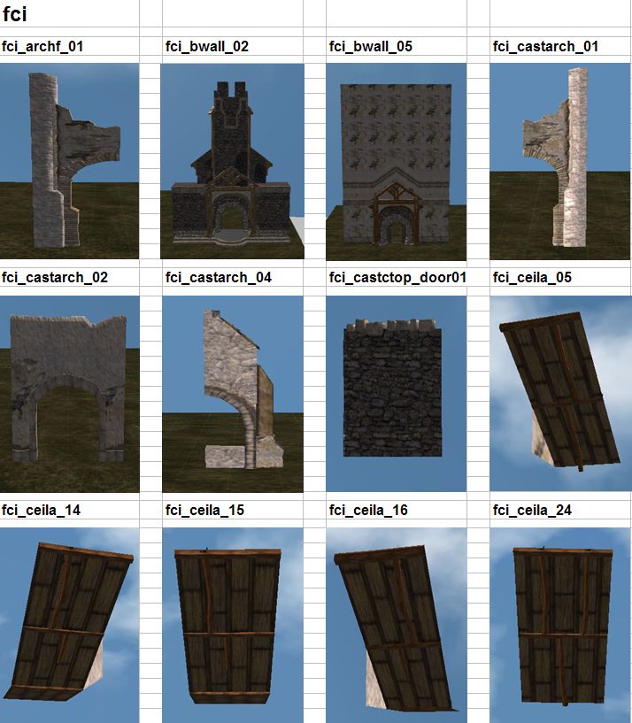
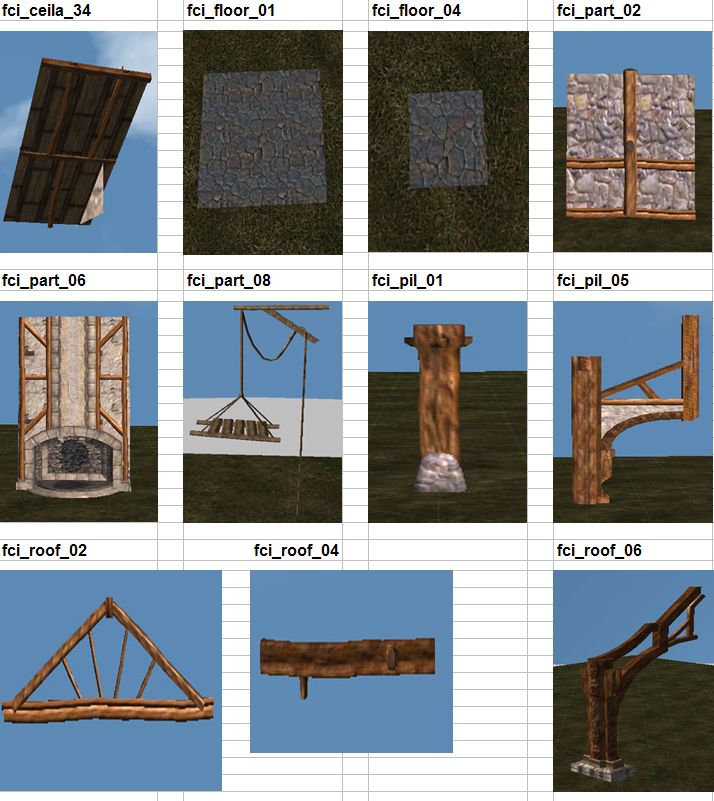
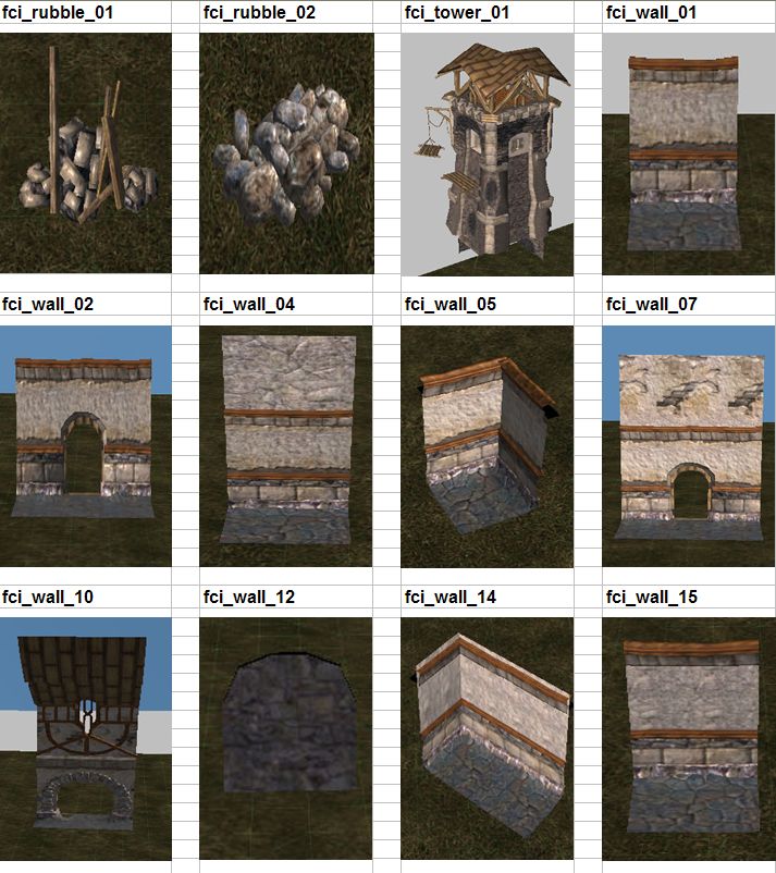
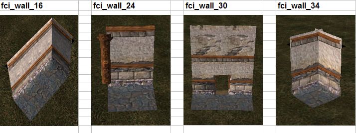
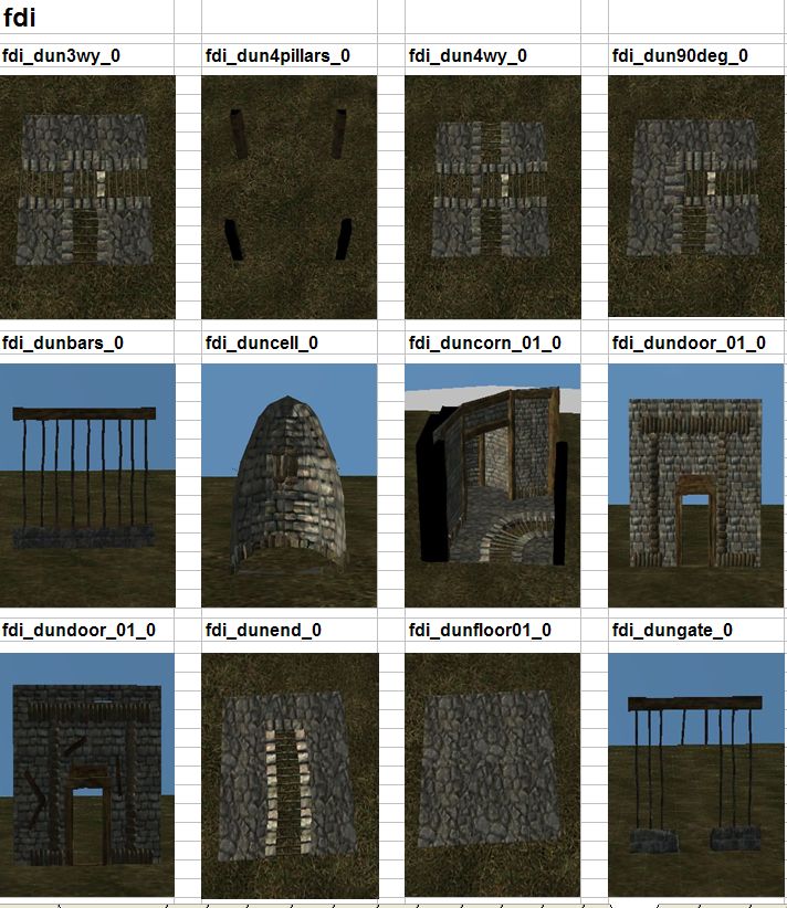
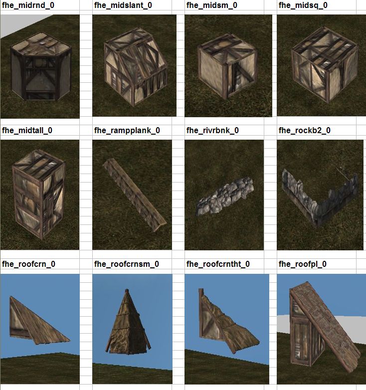
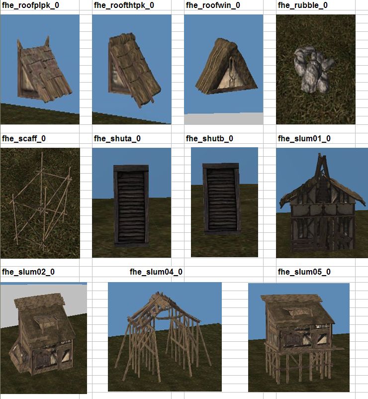
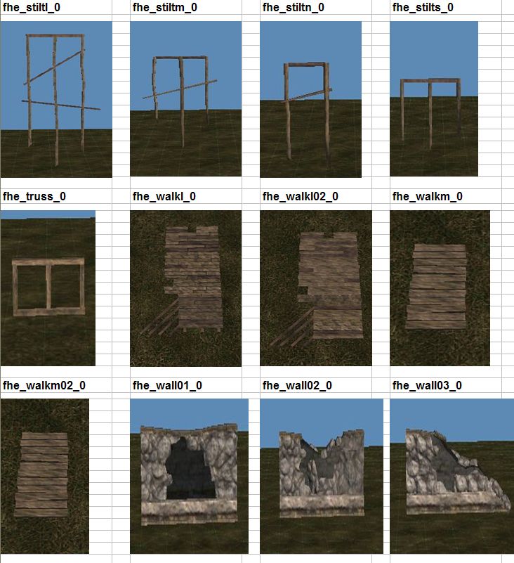
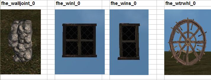
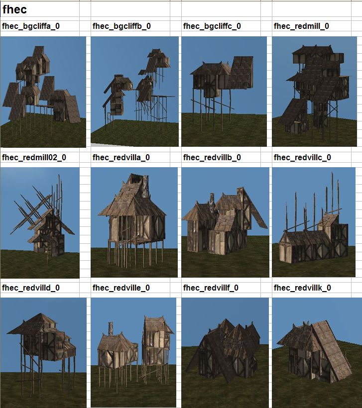
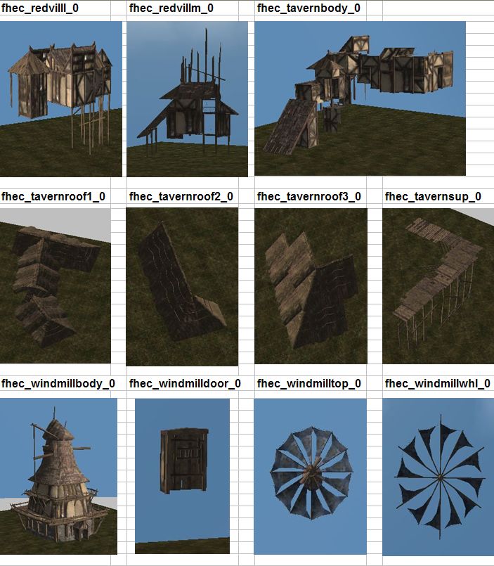
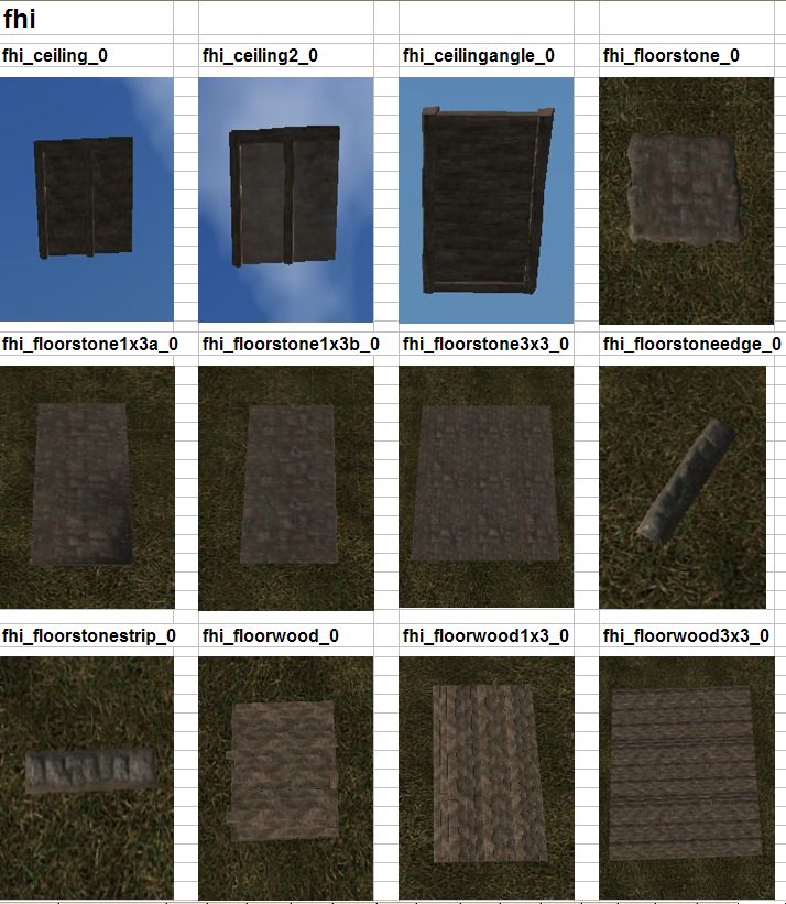
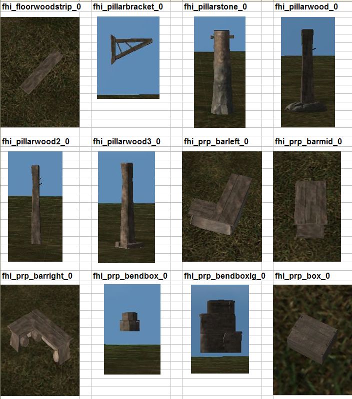
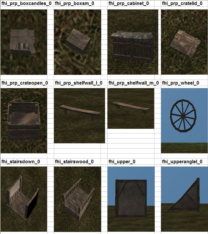
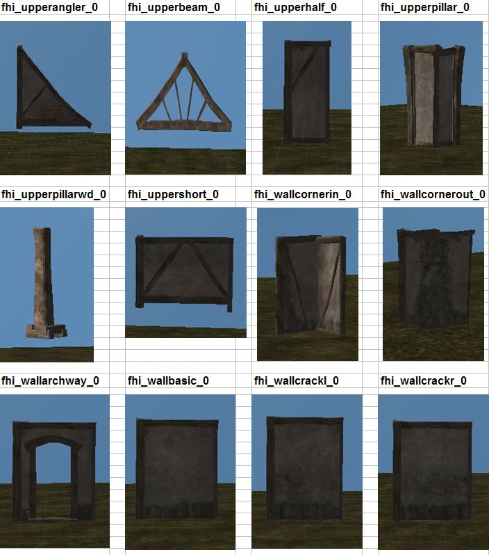
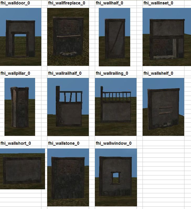
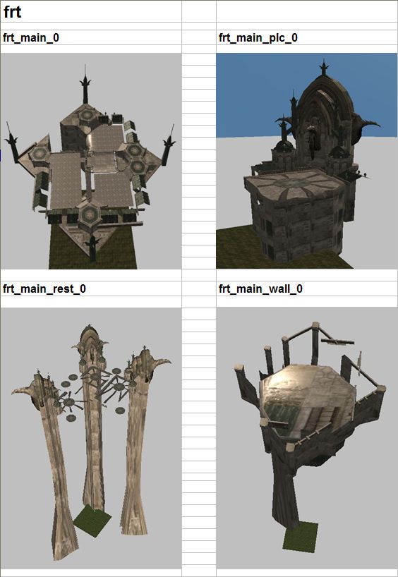
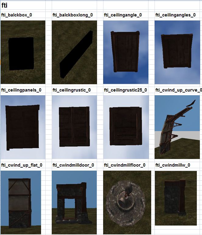
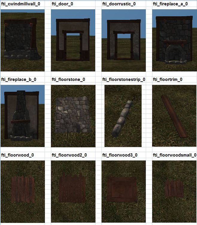
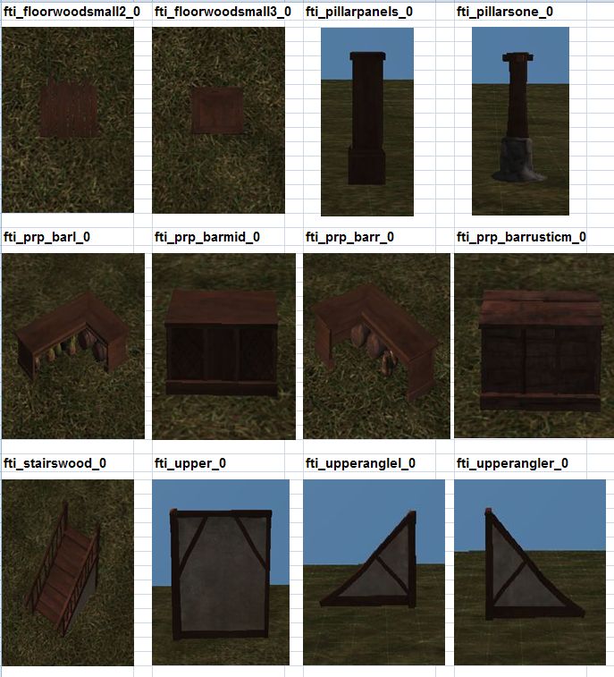
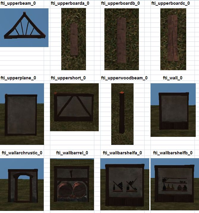
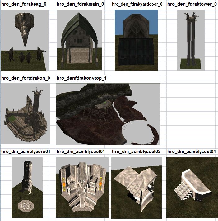
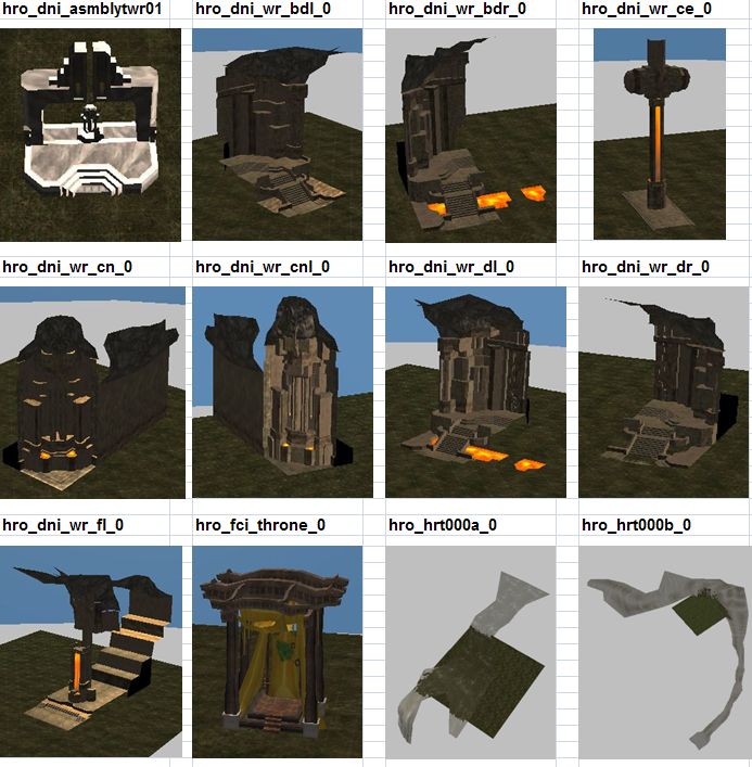
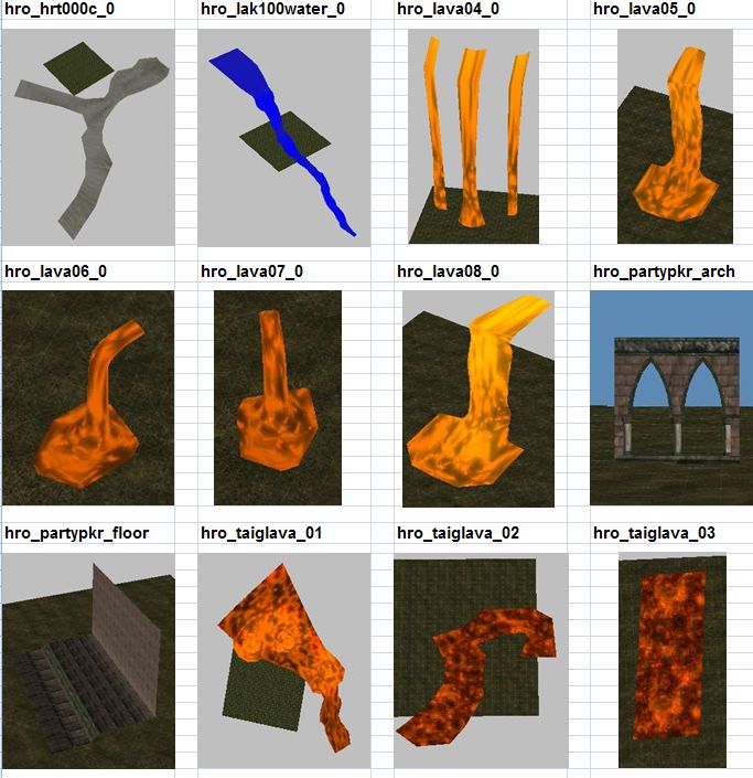
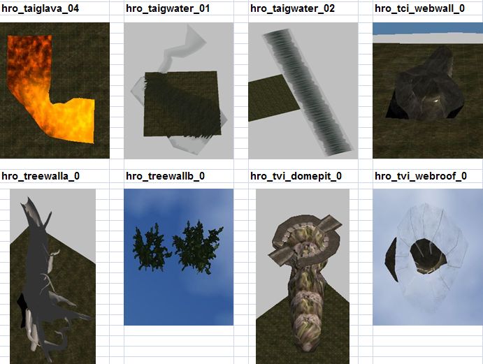
Level Editor Models
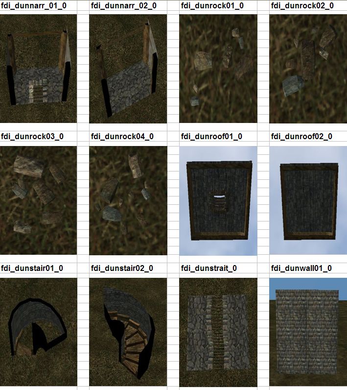
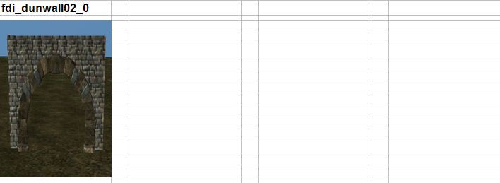
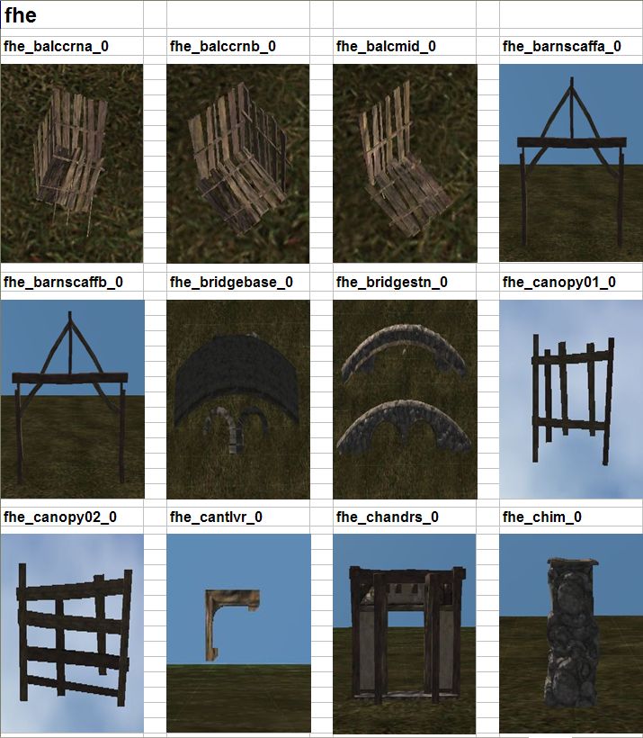
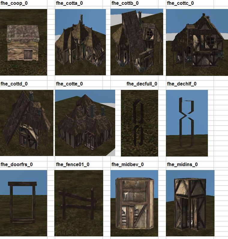
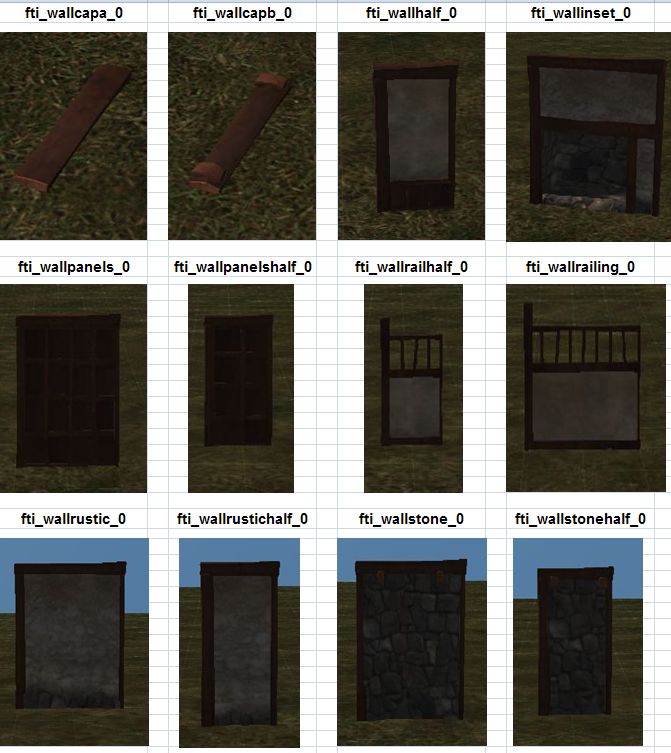
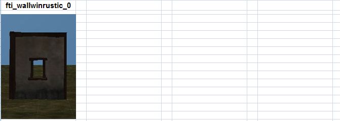
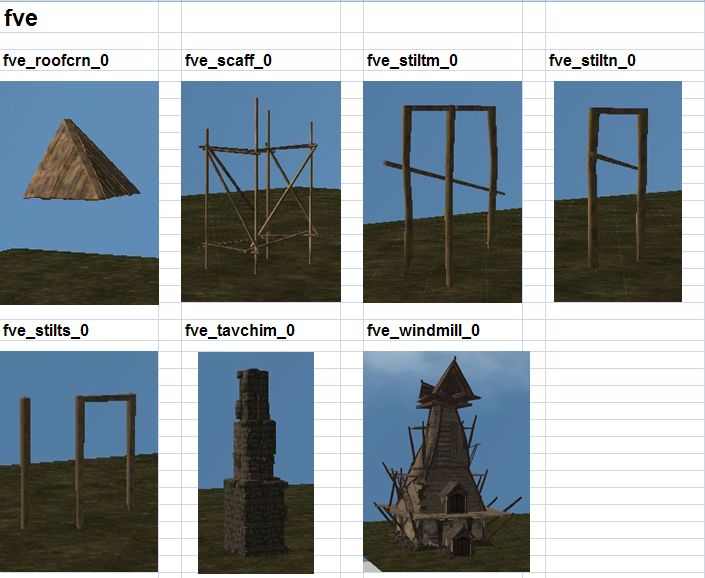
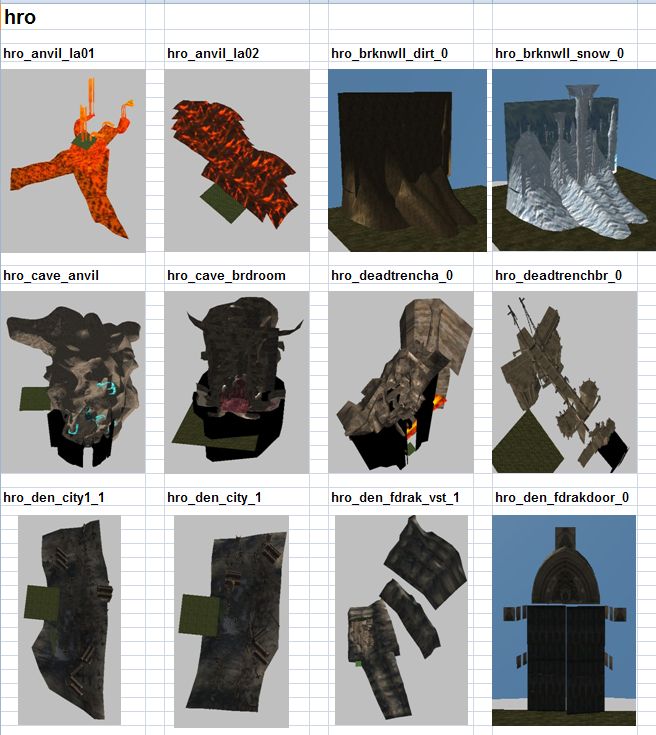
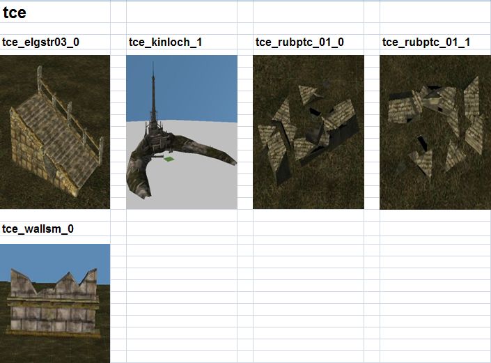
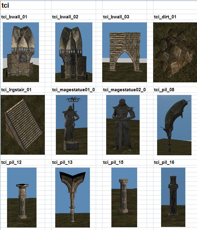
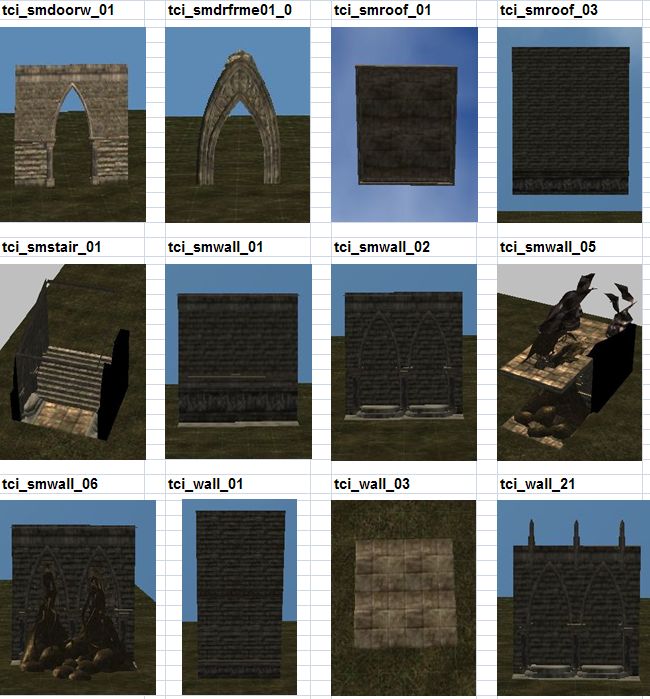
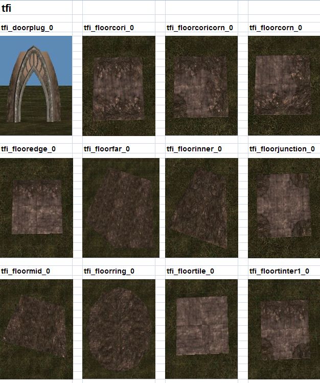
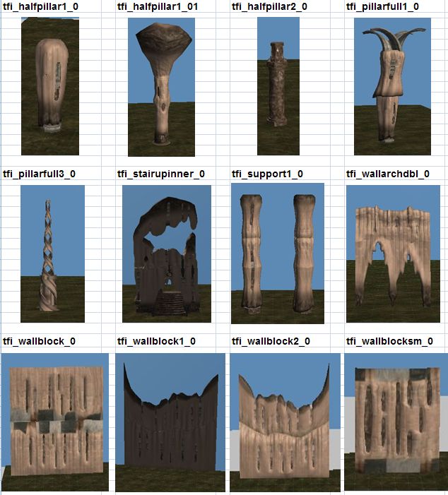
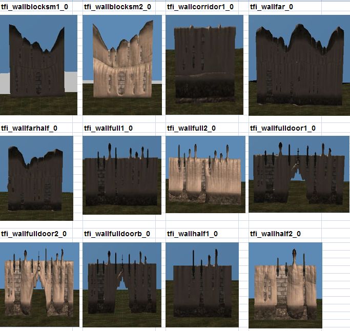
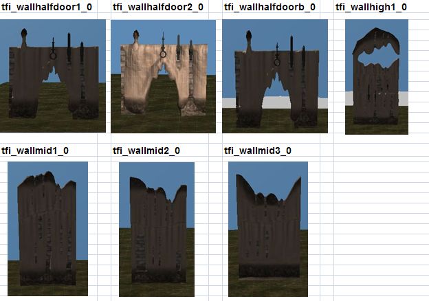
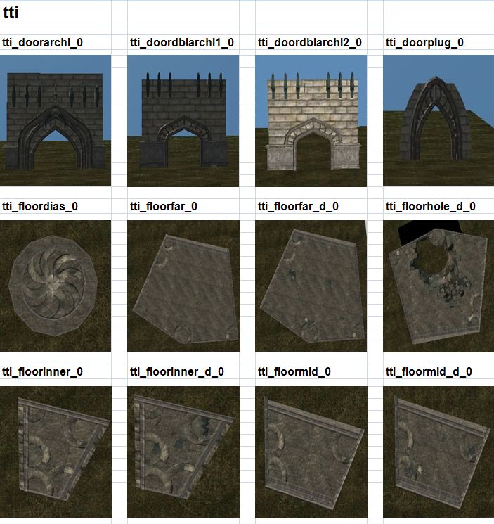
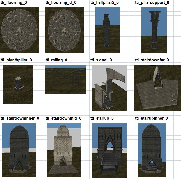
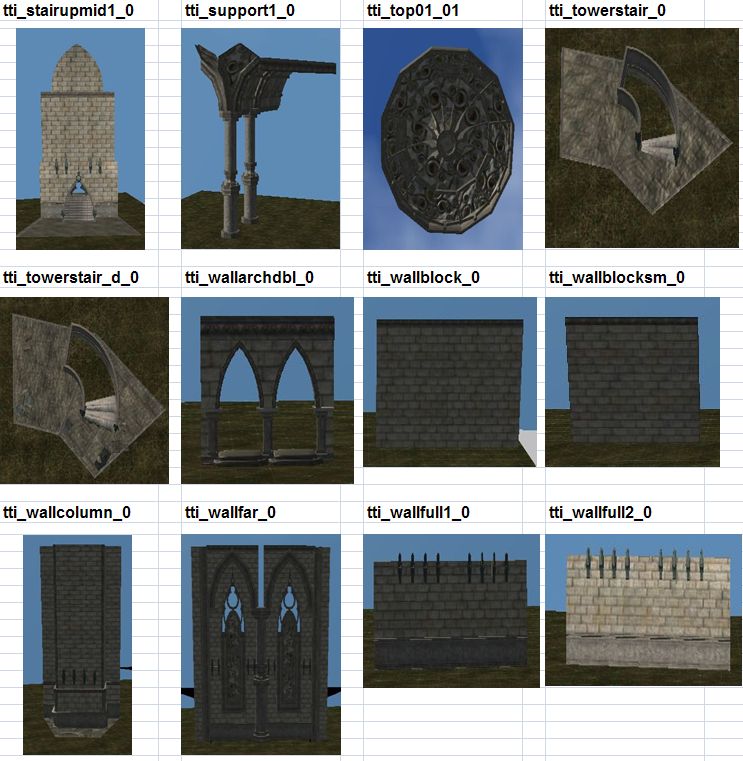
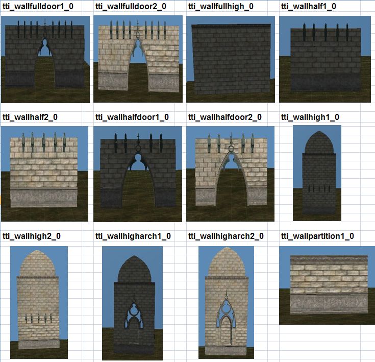
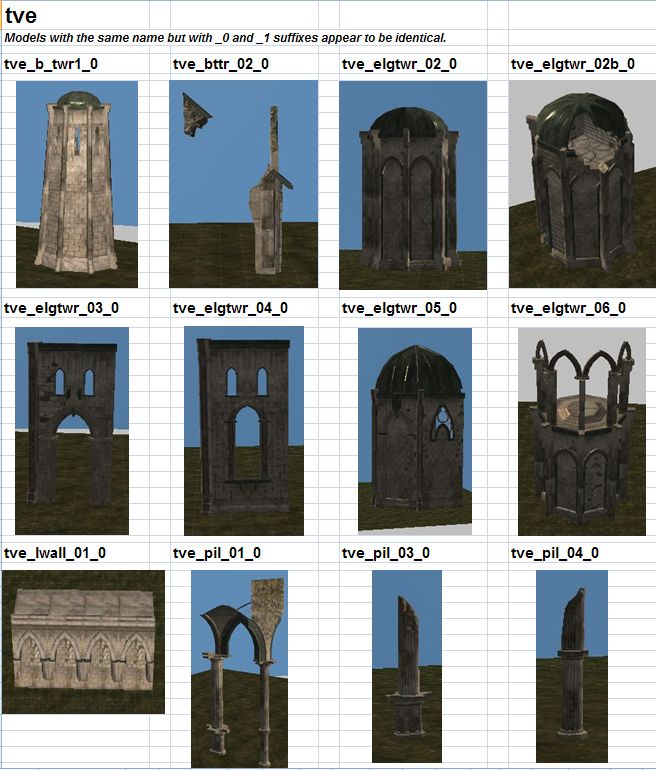
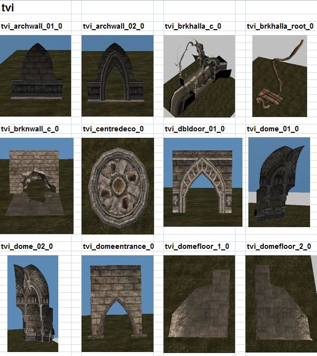
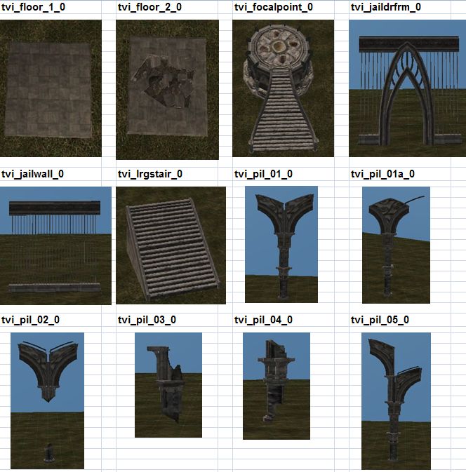
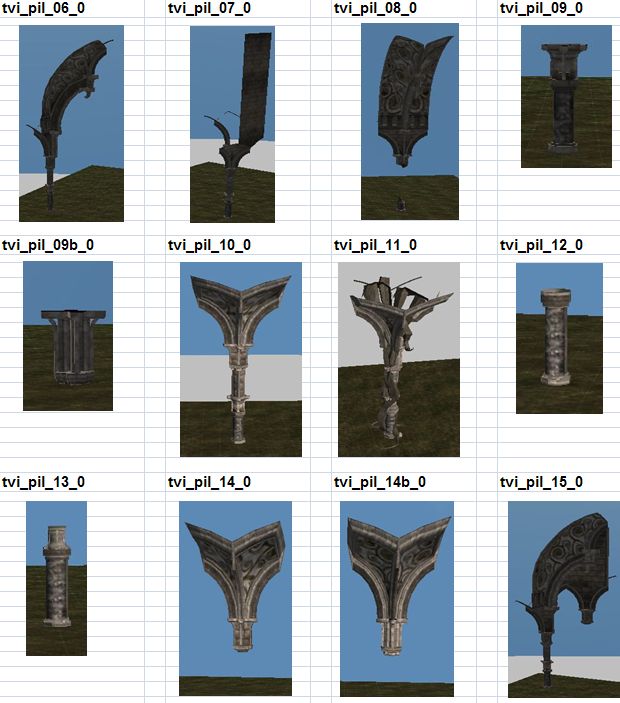
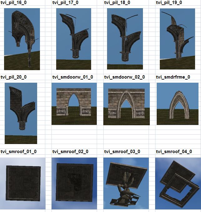
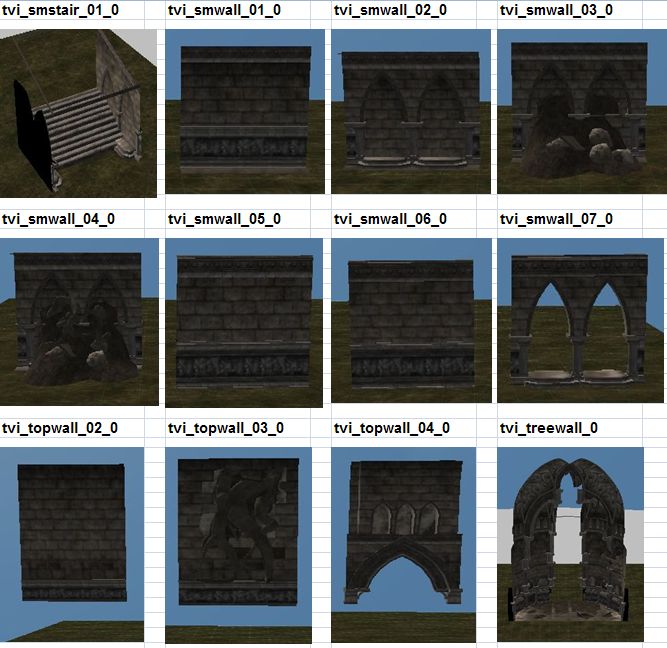
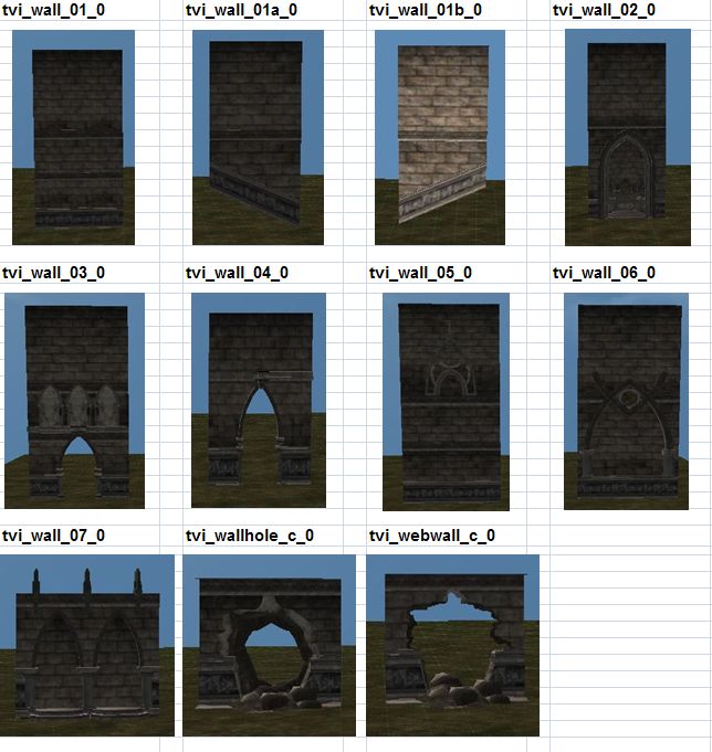
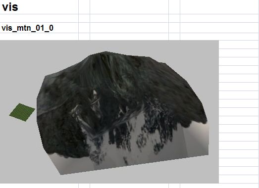
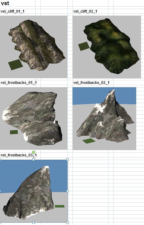
The idea behind showing these models is to give the player a quick view of the actual model that corresponds with a model file name. Most of the files have meaningful names however the builder will still find that he/she has to place the model in the level to see what it looks like. These will allow the builder to quickly view model images and thus save them time in level building.
- Black models are used to surround indoor areas so that players can see inside the walls when the camera is outside them. - All screen shots are taken with a level of 64 x 64 size (smallest size possible). This allows you to see a relative scale of the model. Most are placed within the level area but some are much larger than the area. - Many of these images are not exactly to scale, the idea is to see what the image looks like rather than to see the exact size to scale. - Some model images such as ceilings and roofs will be taken from underneath looking into the sky. - Some model images look the same but are of different size. - Some models extend below the grounds surface when placed. - The models in this sheet are architectural and environmental. Models that are props, placeables, fx, body parts etc can all be viewed in other areas of the toolset.
